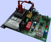
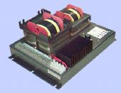
The GM013 AUTOMATIC BATTERY CHARGER is a compact unit designed for internal switchboard mounting. A separate transformer for 12 or 24 Volt use is required. The charging characteristic is initially a constant current which automatically tapers off to a very low level of trickle current as the battery voltage rises towards the charger float voltage output. The float voltage and maximum current output levels are easily preset by controls on the unit.
A boost condition can be introduced which causes the full constant current to flow (irrespective of battery
voltage). A boost timer is incorporated which resets the charger to normal automatic float charging
irrespective of the position of the boost switch, after four hours.
A Red Light Emitting Diode (LED) signals Reverse Polarity battery connection. A Green LED shows the
charge status. While the Green LED is On, or Flashing, the battery is being charged. When the Green LED
is Off or flashing periodically, the battery has reached the preset Float Voltage.
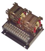
NOTE: These chargers do not come with a transformer. Suitable transformers are listed below.
Datasheet: Download
SPECIFICATIONS
| Input supply: | For 12VDC, 17VAC, for 24VDC, 33VAC |
| Output voltage: | 12 or 24VDC (specify on order) |
| Output current: | nominal 4A (determined by transformer rating) |
| Operational temperature range: | 0 – 60 C ambient |
| Control potentiometer 1: | set float voltage (factory preset) |
| Control potentiometer 2: | set maximum current (factory preset) |
CALIBRATION
- With a voltmeter across terminals 1 and 2, and an ammeter from terminal 1 to battery positive, switch the battery charger into BOOST mode by switching terminals 2 and 3.
- Adjust the SET MAX CURRENT potentiometer so that the ammeter indicates 4A.
- Turn off the BOOST mode.
- Adjust the SET FLOAT VOLTAGE (13.5V for 12V nom; 27.5V for 24V nom) so that the output current is about 0.5A with no external load to the values above. This completes the calibration


Reviews
There are no reviews yet.